Understanding the flow diagrams of cryogenic Air Separation Units (ASUs) is crucial for anyone involved in the industrial gas production sector, whether you're an engineer, a technician, or a decision-maker in a company that relies on these systems. As a cryogenic ASU supplier, I've had the privilege of working closely with these complex systems and helping clients decipher their flow diagrams. In this blog post, I'll share some insights on how to understand these diagrams effectively.
The Basics of Cryogenic ASUs
Before diving into the flow diagrams, it's essential to have a basic understanding of what cryogenic ASUs are and how they work. Cryogenic ASUs are industrial plants used to separate atmospheric air into its primary components, such as nitrogen, oxygen, and argon, through a process called cryogenic distillation. This process involves cooling the air to extremely low temperatures, typically below -150°C, where the different components of air liquefy at different temperatures, allowing for their separation.

The key components of a cryogenic ASU include an air compressor, a pre - purification system, a heat exchanger, a distillation column, and storage tanks for the separated gases. Each of these components plays a vital role in the overall process, and their interactions are depicted in the flow diagrams.
Reading the Flow Diagrams
Flow diagrams of cryogenic ASUs are graphical representations that show the sequence of operations and the flow of materials and energy through the system. Here are some steps to help you understand them:
1. Identify the Key Components
Start by looking for the major components of the ASU in the diagram. The air compressor is usually one of the first components, as it takes in atmospheric air and compresses it to a higher pressure. The pre - purification system, which removes impurities such as water vapor, carbon dioxide, and hydrocarbons, is typically located after the compressor. The heat exchanger, where the compressed and purified air is cooled to cryogenic temperatures, is another crucial component. The distillation column, where the actual separation of the air components occurs, is often the centerpiece of the diagram.
For example, in a well - designed flow diagram, you can easily spot the air compressor as a large block with arrows indicating the intake of atmospheric air and the output of compressed air. The pre - purification system might be shown as a series of smaller blocks or chambers, each representing a different purification step.
2. Follow the Material Flow
Once you've identified the components, follow the arrows in the diagram to understand the flow of materials. The atmospheric air enters the system through the air compressor, then moves through the pre - purification system, and finally into the heat exchanger. After being cooled, the air enters the distillation column, where it is separated into its components. The separated gases, such as nitrogen and oxygen, then flow out of the distillation column and into storage tanks or directly to the end - users.
It's important to note that in some cryogenic ASUs, there may be recycling loops or additional processing steps. For instance, some of the waste gases from the distillation column may be recycled back into the system to improve efficiency.

3. Understand the Energy Flow
In addition to the material flow, cryogenic ASUs also involve a significant amount of energy transfer. The air compressor requires a large amount of electrical energy to compress the air. The heat exchanger transfers heat between the incoming and outgoing streams to cool the air to cryogenic temperatures. The distillation column also requires energy to maintain the proper temperature and pressure conditions for separation.
Look for symbols or annotations in the flow diagram that indicate energy sources, such as electrical power lines or heat transfer arrows. Understanding the energy flow is essential for optimizing the operation of the ASU and reducing energy consumption.
Specific Components and Their Functions in the Flow Diagram
Air Compressor
The air compressor is the starting point of the cryogenic ASU process. It takes in atmospheric air, which is a mixture of nitrogen (about 78%), oxygen (about 21%), and small amounts of other gases such as argon, carbon dioxide, and water vapor. The compressor increases the pressure of the air, typically to several bar, which is necessary for the subsequent purification and cooling steps.
In the flow diagram, the air compressor is often shown as a large, power - consuming unit. The compressed air then flows to the pre - purification system.
Pre - purification System
The pre - purification system is designed to remove impurities from the compressed air. Water vapor and carbon dioxide can freeze at cryogenic temperatures and cause blockages in the heat exchanger and distillation column. Hydrocarbons can also pose a safety hazard in the cryogenic environment.
The pre - purification system usually consists of adsorption beds filled with materials such as molecular sieves, which can selectively adsorb water vapor, carbon dioxide, and hydrocarbons. In the flow diagram, you may see multiple adsorption beds arranged in parallel or series, along with valves to control the flow of air through the beds.
Heat Exchanger
The heat exchanger is a critical component in the cryogenic ASU, as it cools the compressed and purified air to cryogenic temperatures. It works by transferring heat between the incoming warm air and the outgoing cold gases from the distillation column.
There are different types of heat exchangers used in cryogenic ASUs, such as plate - fin heat exchangers and tube - and - shell heat exchangers. In the flow diagram, the heat exchanger is shown as a complex network of tubes or plates, with arrows indicating the flow of the warm and cold streams.
Distillation Column
The distillation column is where the actual separation of the air components occurs. Based on the different boiling points of nitrogen, oxygen, and argon, the distillation column operates at cryogenic temperatures and specific pressure conditions.
The column is usually divided into multiple stages, with trays or packing materials to enhance the mass transfer between the liquid and vapor phases. The nitrogen, which has a lower boiling point, rises to the top of the column, while the oxygen, with a higher boiling point, collects at the bottom. Argon, which has a boiling point between nitrogen and oxygen, is usually separated in a secondary column.
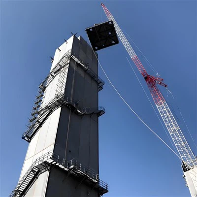
In the flow diagram, the distillation column is shown as a tall, vertical structure with multiple connections for the input of the cooled air and the output of the separated gases.
Importance of Understanding Flow Diagrams for Different Stakeholders
Engineers
For engineers, understanding the flow diagrams is essential for designing, optimizing, and troubleshooting cryogenic ASUs. By analyzing the flow of materials and energy, engineers can identify potential bottlenecks, improve the efficiency of the system, and ensure its safe and reliable operation.
Technicians
Technicians who operate and maintain cryogenic ASUs rely on the flow diagrams to understand the normal operation of the system and to diagnose problems when they occur. The diagrams help them locate different components, understand the sequence of operations, and follow the proper procedures for startup, shutdown, and maintenance.
Decision - Makers
Decision - makers in companies that use cryogenic ASUs, such as those in the chemical, pharmaceutical, and food industries, need to understand the flow diagrams to evaluate the performance and cost - effectiveness of the systems. By having a clear understanding of how the ASU works, they can make informed decisions about capacity expansion, energy efficiency improvements, and equipment upgrades.
Resources for Further Learning
If you're interested in learning more about cryogenic ASUs and their flow diagrams, there are several resources available. You can visit our website to explore detailed information about Cryogenic Air Separation Nitrogen, Cryogenic Equipment, and Liquid Air Separation Plant. These pages provide in - depth knowledge about the specific components and processes involved in cryogenic ASUs.

Conclusion
Understanding the flow diagrams of cryogenic ASUs is a valuable skill for anyone involved in the industrial gas production industry. By following the steps outlined in this blog post, you can gain a better understanding of these complex diagrams and the processes they represent. Whether you're an engineer, a technician, or a decision - maker, this knowledge will help you optimize the operation of cryogenic ASUs, improve their efficiency, and ensure their safe and reliable performance.
If you're interested in purchasing a cryogenic ASU or have any questions about our products and services, please don't hesitate to contact us for a detailed discussion and personalized solutions.
References
- Perry, R. H., & Green, D. W. (1997). Perry's Chemical Engineers' Handbook. McGraw - Hill.
- Kohl, A. L., & Nielsen, R. B. (1997). Gas Purification. Gulf Publishing Company.
- Schweitzer, P. A. (1997). Handbook of Separation Techniques for Chemical Engineers. McGraw - Hill.